
RESEARCH ARTICLE
Controllable Magnetoactive Polymer Conduit
A. Diermeier1, D. Sindersberger1, L. Krenkel2, X. C. Rosell3, G. J. Monkman1, *
Article Information

Identifiers and Pagination:
Year: 2018Volume: 12
First Page: 192
Last Page: 200
Publisher Id: TOMEJ-12-192
DOI: 10.2174/1874155X01812010192
Article History:
Received Date: 13/6/2018Revision Received Date: 27/8/2018
Acceptance Date: 18/9/2018
Electronic publication date: 23/11/2018
Collection year: 2018
open-access license: This is an open access article distributed under the terms of the Creative Commons Attribution 4.0 International Public License (CC-BY 4.0), a copy of which is available at: (https://creativecommons.org/licenses/by/4.0/legalcode). This license permits unrestricted use, distribution, and reproduction in any medium, provided the original author and source are credited.
Abstract
Objective:
Magneto-active Polymers (MAP) are smart materials whose mechanical characteristics, such as elastic and shear moduli, may be controllable by means of an externally applied magnetic field.
Methods:
Various additives may be used to influence the characteristics of the polymer matrix whilst a suspension of soft and/or hard magnetic particles determine the magnetic properties of the composite. Both pre-cure and post-cure magnetization is possible.
Results:
A range of control strategies have been investigated for evaluation of the system using fluids of differing kinematic viscosity.
Conclusion:
Depending on the degree of magnetic field homogeneity, magneto-deformation and magnetostriction contribute to MAP actuation. This paper presents a novel application in the form of a peristaltic MAP tube system, applicable to flow control and pumping of hemorheological fluids in blood circulatory systems for biomedical research purposes.
1. INTRODUCTION
Over the past decade, Magneto-active Polymers (MAP) have become an established class of hybrid smart material. Magneto-active polymers are closely related to magneto-rheological fluids in that they contain magnetic micro-particles. However, instead of being freely suspended in a carrier fluid, they are physically bound within a highly elastic polymer-matrix. Homogeneity of particle distribution and specific elastic properties of the matrix are achieved by special fabrication processes [1].
The influence of an external magnetic field can produce changes in Young's modulus of over 106% (colossal magneto-rheological effect) [2]. In addition to dramatic changes in mechanical storage and loss moduli, changes in electrical properties are also measurable [3]. In addition to various additives, MAP can be made to contain both soft and hard magnetic particles where pre and post cure magnetization is possible [3, 4].
Hitherto, the main focus of research has been on improving MAP fabrication processes, particularly in terms of reproducibility and macro-, meso- and micro surface structuring [5]. Rheological characterization of MAP is achieved through oscillating rheological measurement techniques while confirmation of magnetic particle distribution homogeneity can be achieved through three-dimensional computed X-ray tomography [6].
Current research concentrates on the controllable compliance offered by MAP volumes. Depending on the degree of magnetic field homogeneity, together with the colossal magneto-rheological effect, contributions from both magnetostriction and magnetodeformation are observed [7].
This paper deals with recent advances in MAP applications in the fields of bio-medical, automation and controllable geometry resulting in the development of a controllable duct system. Furthermore, the magnetically induced constriction of MAP tubes has potential applications in hydraulic valve technology where pulsed magnetic fields may be utilized for pumping applications. This application depends on in-depth research concerning the magneto-active principles which in turn opens new possibilities for further investigation into MAP actuation.
2. PRIOR ART
Magnetorheological Fluids (MRF) have been used in controllable devices for many years. Typical applications include damper systems [8], clutches for torque transfer [9, 10] and braking systems [11].
In contrast to MRF, the magnetic particles in MAP are embedded into an elastic matrix structure, which maintains homogenous particle distribution thus avoiding particle sedimentation problems normally associated with MRFs. This offers new shape memory possibilities such as the retention of complex shape geometries. Nevertheless, MAP damping characteristics remain of interest in fields concerning controlled viscoelastic behaviour [12].
Sensory feedback may be achieved through the combination of piezoelectric devices with MAP thus allowing adjustment of the MAP load by means of a controlled magnetic field [13]. MAP also finds applications in pneumatic valve systems for air flow control. In this system, an annular shaped Magneto Active Elastomer (MAE) body expands radially due to the influence of an applied magnetic field thus closing the gap between the MAE and the valve body [14].
The aim of this research is to establish and control pneumatic and hydraulic flow by means of MAP driven systems.
2.1. Polymer Matrix
MAP is a composite material essentially comprising two components: a polymer matrix and a suspension of magnetically susceptible micro-particles with defined size and shape.
Many different polysiloxanes, also commonly known as silicone, may be used for the matrix. Silicones are available with different viscosities and post-cure elastic moduli. Modification and handling of silicone is simple and inexpensive. However, other polymers/elastomers, such as polyurethane may also be utilised [15]. In this work, the industrial two-component silicones “Sylgard” (Dow Corning), “Elastosil RT60” (Wacker), “SF00” and “ZF13” (Silikonfabrik.de) are used. Table 1 shows a comparison of commercially available compounds.
| Polymer | Characteristics | ||
|---|---|---|---|
| Shore A Hardness | Mixed Viscosity | Pot Life at 23°C | |
| Elastosil RT604 | 25 | 800 | 90 |
| SF00 2K-Silikon | 00 | 1.5000 | 6 |
| Sylgard | 43 | 35.000 | 90 |
| ZK13 2K-Silikon | 13 | 45.000 | 40 |
Commercially available products offer the advantage of stable reproducibility when using mixtures from the same batch, though the often unknown detailed chemical structure can be a disadvantage. For mechanical applications, this challenge is tackled empirically [16]. The basic polymer can be modified by the use of different additional ingredients, such as silicone oil, inhibitor, catalyst or thixotropic additives.
2.2. Magnetic Particles
The second main component is the dispersion of soft or hard magnetic particles. The final characteristics of the magneto active polymer depend not only on the ratio of matrix and particles but also the particle geometry, distribution and orientation [17, 18]. In this work, carbonyl iron powder (Fe(CO)5) “CIP SQ” (BASF) with a diameter distribution of 3.9-5.0µm and spherical morphology is used. Carbonyl iron has an outstanding magnetization behaviour and is well known for utilization in magnetorheological fluids [19].
3. MAGNETO-ACTIVE TUBING
Medical research into the replication of blood circulatory systems requires controllable ducts to simulate real arteries [20] and magneto-active tubing offers new possibilities in this respect.
Particularly important is the replication of systolic medical functions, such as “Windkessel” effect [21]. The highly controllable elastic properties of MAP are ideal for rmulating such functions.
This would be of assistance in investigations into a number of common arterial diseases. An aneurysm is a localized arterial dilation which can be replicated by a magnetic field induced deformation of MAP tubing. This kind of actuator also simplifies investigations into the effects of arterial narrowing.
3.1. Operating Principle
Under the influence of an applied magnetic field from an electromagnet, a strong deformation of the MAP structure, leading to a constriction of the tube, can be observed as shown in Fig. (1).
 |
Fig. (1). MAP tube a) without B-field, b) with 200mT B-field, c) with 450mT B-field. |
Constriction forces depend on both the magnetic field strength and the characteristics of the MAP see Fig. (1). Current research concerns constriction optimization for hydraulic valve suitability. In addition, a pulsed magnetic field may be utilised for pumping applications.
3.2. Fabrication Processes
The MAP tubes are based on a polymer mixture of two different silicones, each with different post curing elasticity. The magnetic particles are added to the liquid polymer mixture prior to degassing. Due to the very short post-mix pot-life of the compound, an inhibitor [22] may be used to extend the degassing process.
Following initial degassing, the mixture is cast in a Polytetrafluorethylene (PTFE) coated stainless steel mould. Due to the temperature dependency of the curing rate, the mould is cooled to -5°C in order to retard the curing process. A second degassing process (<5 x 10⁻³ mBar) reduces air inclusions after casting. Curing takes place in a temperature controlled oven at 70°C for 12 hours. Finally, the casting is allowed to slowly cool to room temperature (approximately 22°C) before the tube is removed from the mould.
4. ELECTROMAGNETIC CONTROL
Initial tests were carried out using a simple magnetic circuit. The magnetic field gradient is maximised in the vicinity of the 1.5 mm air gap which in turn results in a deformation of the MAP without achieving full constriction of the annular tube geometry. An empirical study revealed a 3mm gap to have the optimum characteristics for fully sealed tube closure.
In order to maintain the tube closed, a magnetic flux density of 450mT (measured at the centre of the gap) is required, which equates to a continuous power consumption of approximately 7 Watts. This can be reduced by a suitable magnetic circuit design.
An alternative is to employ NdBFe permanent magnets to provide a continuous magnetic field, which may be negated by means of a short inductively induced magnetic pulse. This allows the design of both “normally open” and “Normally Closed” (Fig. 2) valves, which significantly reduce energy consumption.
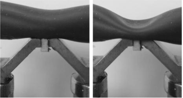 |
Fig. (2). MAP tube open (left) and “Normally Closed” (right). |
4.1. FEM-Simulation
Further optimisation of the yoke concept was performed in order to achieve actuation suitable for peristaltic pumping by means of a phase-shifted electro-magnetic control system. To these ends, Comsol Multiphysics finite element simulation was used to analyse and optimize the yoke design.
The FEM-model is based on a three-dimensional CAD model of the magnetic circuit shown in Fig. (3), which comprises an iron yoke with a 3mm acrylic filled gap. A MAP-tubular device, having an inner diameter of 9mm and a wall thickness of 1.5mm, is mounted on top of the yoke. In order to reduce FEM solving time, two-dimensional modelling was performed.
 |
Fig. (3). CAD model of the yoke design used. |
A stationary magnetic field simulation was used to investigate the magnetic flux in the yoke and MAP tube, generated by two coils. Fig. (4) shows a surface plot of the magnetic flux density in the gap, part of which is induced into the MAP tube.
 |
Fig. (4). Surface magnetic flux density [T] in and around the gap. |
A solid mechanics simulation is coupled to the magnetic field simulation by means of force calculation nodes using the Maxwell surface stress tensor.
 |
(1) |
The mechanical force necessary for constriction of the MAP-tube is provided by the magnetic force caused by the magnetic field gradient in the vicinity of the yoke gap. Magnetic force is calculated by multidimensional integration, where "n" is the surface normal of the plane of the object on which the force acts. T is the strain tensor and S is defined as the Poynting vector, which represents the directional energy flux density (rate of energy transfer per surface area) of the electromagnetic field [23]. For each MAP-tube domain, a separate boundary load node was inserted in the solid mechanic simulation. The Maxwell surface stress tensors, resulting from the mf-force calculation nodes, are chosen as load type, separately for the upper and lower tube cross-sectional areas. A fixed constrained node at both ends of the tube geometry mechanically secures the polymer tube. A second fixed constraint is used at the upper surface of the yoke, which provides the contact force surface.
The mechanical properties of the MAP material must be included in the FEM material database to make simulation of the tube surface displacement possible. Both, elastic modulus and shear modulus of the MAP compound are functions of the magnetic flux density. These were measured by an oscillation rheometer (Anton Paar MCR 301) with a special magnetorheological cell [16] and inserted to the FEM database by means of interpolated curves.
The FEM simulation of the yoke assists in optimizing the system design and improving closure of the annular tubing at higher flux densities. Consequently, a valve application based on MAP-tube is clearly feasible.
4.2. Peristaltic Pump
Conventional peristaltic pump systems are based on rotating rollers, assembled in a star configuration and use positive displacement for pumping various fluids, particularly in biomedical fields. This causes a sectional constriction of an elastomeric tube, which leads a movement of fluid in the tube by a squeezing action. Furthermore, the rollers subject the tube outer surfaces to continuous frictional wear. In contrast, using magnetic fields for tube constriction, deformation is achieved without mechanical friction or the movement of rigid parts [24].
Three magnetic circuits (Fig. 5) were assembled with an offset making sectional constriction of the MAP-tube possible. Each coil had an inductance of 12 mH and an internal resistance of 11 Ω, giving a time constant of 132 ms. The electromagnetic coils may be controlled by a microcomputer or PLC. Each cycle consists of six on/off phases (Fig. 5), where coil switching is achieved using a Gray-code sequence.
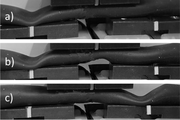 |
Fig. (5). Peristaltic pump - a) phase I, b) phase II, c) phase IV. |
The system allows fluid transport in a peristaltic manner but without the severe compressive forces experienced by conventional peristaltic pumps. This is important in medical applications where excessive shear forces, induced by peristaltic pumps can result in the rupture of red blood cells (so-called hemolysis) which is highly undesirable [25]. Furthermore, the MAP concept makes more physiological pulsatile flow regimes possible. This has advantages over the generally steady flow characteristics delivered by conventional peristaltic or radial pumps, and in addition, with considerably reduced shear forces.
An optimization of the control system in terms of more physiological pulsatile flow with lower shear forces can be achieved by applying sinusoidal current controlled magnetic field sequences to allow for smoother and adjustable fluid transport.
As a further application in biomedical engineering, MAPs can be employed as rapidly acting adjustable valves in experimental configurations for the investigation of pulsatile flow regimes in compliant vessel phantoms. Computer-driven linear motor pumps can be used to generate realistic, human heart-like volume flow characteristics in elastic vessel circulatory system models. The resulting pressure curve is dominated by the compliance and complexity of the complete circulatory vessel system. Since the applied vessel phantom is usually less complicated than a realistic circulatory system, experimental pressure curves do not follow physiological pressure curves. In preliminary tests, it has been shown, that a rapidly reacting MAP valve can be used to modulate the pressure induced by the computer-controlled volume driven motor-pump. This results in more realistic pressure characteristics within the vessel section under investigation.
5. EXPERIMENTAL RESULTS
Using a WAGO PLC with two 750-502 digital dual output modules [25], simple Pulse Width Modulation (PWM) control can be exercised. When the duct is to be used as a pump, class D modulation allows control of both duty cycle and frequency.
| Duty cycle/frequency | 0.5 Hz | 1 Hz | 2 Hz |
|---|---|---|---|
| 40% | Stationary | Forward | Reverse |
| 60% | Forward | Reverse | Stationary |
| 70% | Stationary | Forward | Forward |
| 90% | Stationary | Forward | Reverse |
These parameters can be used to determine the flow rate and flow direction as shown in Table 2. Exact pulse parameters are however subject to tube dimensions and carbonyl iron content of the MAP. At 4 Hz and above, pump motion ceases regardless of the pulse width.
Where the magnetoactive polymer contains only soft magnetic particles and no permanent magnetic biasing is employed then unipolar magnetic fields may be generated with a single current flow direction using class C modulation, whereas full bipolar control normally requires class A modulation with significantly lower efficiency. An alternative for sinusoidal bipolar control uses PWM as shown in Fig. (6) [26].
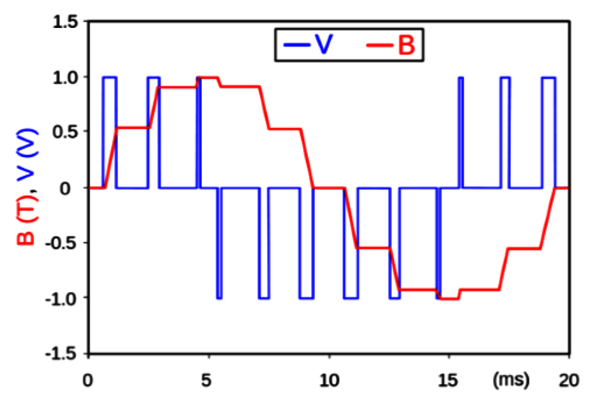 |
Fig. (6). Semi-sinusoidal signal generated by PWM. |
This results in more precise rate control without sacrificing much power efficiency. Care must be taken to drive the circuitry at a rate well within the time constant of 132 ms but not faster than the switching frequency of the output modules (typically 5 kHz).
The ducts were tested using both water and silicone oil with kinematic viscosities of approximately 10-5 m2/s and 10-6 m2/s respectively. Most hemorheological substances lie between these limits.
 |
(2) |
According to expression {2}, the Reynolds factor lies between 10 and 100 for flow velocity of 1 cm/s. Even with a velocity an order of magnitude higher, the flow remains laminar.
CONCLUSION
The use of magnetoactive polymers, combined with permanent and electromagnets, has resulted in viable pumps and valves suitable for use with fluids, including hemorheological aggregates. The problems of material fatigue, common with many conventional pumps, are considerably reduced. The rapid response of magnetoactive polymers can be used to optimise designs using pulsed and/or sinusoidal control. The current system is potentially suitable for the modelling and emulation of artificial blood circulatory systems. Miniaturization to “lab on a chip” scales is also conceivable due to the simplicity of MAP fabrication using 3D printing.
CONSENT FOR PUBLICATION
Not applicable.
CONFLICT OF INTEREST
The authors declare no conflict of interest, financial or otherwise.
ACKNOWLEDGEMENTS
This work was supported by the German Research Federation (DFG) [SPP1681, 2016]; and the Institute of Applied Research and Partnership with Industry (OTHR) [EBACIM, 2016].
REFERENCES
| [1] | Forster E, Mayer M, Monkman G, Chamonine M. Surface control of magneto active polymer First international conference on Electromechanically Active Polymer (EAP) transducers & artificial muscles 2011. |
| [2] | Stoll A, Mayer M, Monkman GJ, Shamonin M. Evaluation of highly compliant magneto-active elastomers with colossal magnetorheological response. J Appl Polym Sci 2014; 131: 39793. |
| [3] | Sorokin VV, Ecker E, Stepanov GV, et al. Experimental study of the magnetic field enhanced Payne effect in magnetorheological elastomers. Soft Matter 2014; 10(43): 8765-76. |
| [4] | Böse H, Hesler A, Monkman G. Magnetorheologische Kompositmaterialien mit hartmagnetischen Partikeln, Verfahren zu deren Herstellung sowie deren Verwendung Patent H01F 1/08 ; H01F 1/117, 2007. |
| [5] | Forster E, Mayer M, Rabindranath R, et al. Patterning of ultrasoft, agglutinative magnetorheological elastomers. J Appl Polym Sci 2013; 128: 2508-15. |
| [6] | Gundermann T, Odenbach S. Investigation of the motion of particles in magnetorheological elastomers by X- μ CT. Smart Mater Struct 2014; 23: 105013. |
| [7] | Allahyarov E, Menzel AM, Zhu L, Löwen H. Magnetomechanical response of bilayered magnetic elastomers. Smart Mater Struct 2014; 23: 115004. |
| [8] | Li F, Wei G, Qi W, Xinhe X. Modeling and adaptive control of magneto-rheological buffer system for aircraft landing gear. Appl Math Model 2015; 39: 2509-17. |
| [9] | Böse H, Gerlach T, Ehrlich J. Magnetorheological torque transmission devices with permanent magnets. J Phys Conf Ser 2013; 412: 12050. |
| [10] | Rizzo R, Musolino A, Bucchi F, Forte P, Frendo F. A multi-gap magnetorheological clutch with permanent magnet. Smart Mater Struct 2015; 24: 75012. |
| [11] | Rossa C, Jaegy A, Micaelli A, Lozada J. Development of a multilayered wide-ranged torque magnetorheological brake. Smart Mater Struct 2014; 23: 25028. |
| [12] | Lockette PRv, Kadlowec J, Koo J-H. Development of tubable vibration absorbers using magnetorheological elastomers with bimodal particle distributions. 168th Technical Meeting of the Rubber Division 2015, ; 86-99. |
| [13] | Zhou GY, Wang Q. Design of a smart piezoelectric actuator based on a magnetorheological elastomer. Smart Mater Struct 2005; 14: 504-10. |
| [14] | Bose H, Rabindranath R, Ehrlich J. Soft magnetorheological elastomers as new actuators for valves. J Intell Mater Syst Struct 2012; 23: 989-94. |
| [15] | Dohmen E, Boisly M, Borin D, et al. Advancing towards polyurethane-based magnetorheological composites. Adv Eng Mater 2014; 16: 1270-5. |
| [16] | Diermeier A, Monkman GJ. Fabrication and Dynamic Properties of Magneto Active Polymers. ARC Conference Nürnberg. 2015.2015. |
| [17] | Stepanov G, Borin D, Odenbach S. Magnetorheological effect of magneto-active elastomers containing large particles. J Phys Conf Ser 2009; 149: 12098. |
| [18] | Günther D, Borin DY, Günther S, Odenbach S. X-ray micro-tomographic characterization of field-structured magnetorheological elastomers. Smart Mater Struct 2012; 21: 15005. |
| [19] | BASF SE. Carbonyl Iron Powder: Product Overview, 2015. www.monomers. basf.com/ cm/ internet/ en/ function/ conversions:/ publish/ content/ Produkte/ Metallsysteme/ CIP/ CIP_General_PO_e.pdf |
| [20] | Fricke D, Kraitl J, Ewald H. Blood circulatory system for noninvasive diagnostics GL Coté (Ed), SPIE BiOS, SPIE, 85910 2013. |
| [21] | Westerhof N, Lankhaar J-W, Westerhof BE. The arterial Windkessel. Med Biol Eng Comput 2009; 47(2): 131-41. |
| [22] | Evonik Hanse Gmb H. Technology platform: Addition curing silicones: Inhibitors, 2016, http:// corporate. evonik.com /en/ products/ search -products/ pages/ product- details.aspx |
| [23] | Comsol. Magnetic Fields Interface. Comsol (Ed.), Solid Mechanics Module: User’s Guide, pp. 170-259, 2015. |
| [24] | Vasilyeva MA. Perspectives of application of 3D shape memory composite materials for peristaltic transportation of slurries. KEM 2016; 685: 291-4. |
| [25] | Moen O, Fosse E, Bråten J, et al. Roller and centrifugal pumps compared in vitro with regard to haemolysis, granulocyte and complement activation. Perfusion 1994; 9(2): 109-17. |
| [26] | WAGO Modular I/O-SYSTEM. 2-Channel Digital Output Module DC 24 V. 01.04.2009. |
| [27] | Rosell XC. Improvement of a magnetoactive polymer pump Bachelor Thesis, OTH-Regensburg: Universitat Polytechnicade Catalunya, July 2017. |